The Fizeau interferometer is a common type of interferometer, named after F. (H. Fi zeau 1819 - 1896).
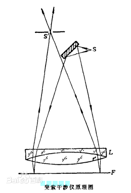
The basic principle optical path is shown in the figure. After the light of the point source S is collimated, the observed transparent object is irradiated near normal incidence, the light is reflected multiple times between the upper and lower surfaces of the object, and the interference fringe is observed from the reflection direction S'. Optical factories use this interferometer to verify the uniformity of glass thickness or the flatness of the surface (optical glass, ceramics, metal surfaces, etc.).
The Fizeau interferometer is a precision instrument that uses equal-thickness interference to detect the shape of an optical component, the wavefront aberration of an optical lens, and the uniformity of optical materials. The measurement accuracy is generally λ/10 to λ/100, and λ is the average wavelength of the light source for detection.
The Fizeau interferometer has both a plane and a spherical surface. The former consists of a beam splitter, a collimating objective lens, and a standard plane. The latter consists of a beam splitter, a finite conjugate objective lens, and a standard spherical surface. The monochromatic beam is on a standard plane or a standard sphere, partially reflected as a reference beam, partially transmitted and passed through the device under test as a detection beam. The detection beam returns automatically and coincides with the reference beam to form equal thickness interference fringes. The surface shape and uniformity of the plate or prism can be detected with a Fizeau plane interferometer. With the Fizeau spherical interferometer, the spherical surface shape and its radius of curvature can be detected. The latter has a measurement accuracy of about 1 micron; it can also detect the wavefront aberration of an infinite, finite conjugate lens.
Like the Taiman-Green interferometer, the Fizeau interferometer also uses an amplitude splitting method: the incident light is incident perpendicular to the reflecting surface. That is, I=0, keeping the incident angle constant, and generating equal-thickness interference fringes to measure the error of the optical component.
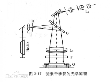
Figure 2-1 shows the optical path of the Fizeau interferometer. A monochromatic source such as a HeNe laser illuminates the aperture H to form a point source. The light beam emitted from the point source is reflected by the beam splitter G, is directed toward the lens L2, becomes a parallel beam, and then is directed perpendicular to the standard flat crystal P. A part of the light is reflected by the upper surface of P, and another part of the light is transmitted to the device under test Q through P. After the light beam reflected by the upper surface of Q and the light beam reflected by the upper surface of P enter the observation system, equal thickness interference fringes are generated to measure the surface shape error of the upper surface of Q. If the standard flat crystal P is changed to a spherical surface, that is, the lower surface is a spherical surface, the surface shape error of the spherical surface can be measured. By removing the standard member P and interfering with the light beam reflected from the upper and lower surfaces of the device under test Q, the parallelism of Q can be measured.
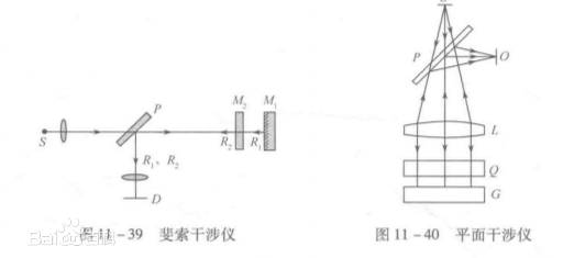
In the Fizeau interferometer shown in Figures 11-39 below, the plane mirrors M1, M2 are placed on the same optical path. The incident light passes through the flat half mirror P and then reaches the plane mirror M1. M2 is also a transflective mirror; such that part of the light is reflected back to the flat plate P by M2 (R2 is used as reference light), and the other part is reflected by M2 to the reflection. After the mirror M1 (R1 as the sensing light), it is reflected back to the flat panel P, and the two beams coincide to form an interference.
It can be seen that the biggest difference between the Fizeau interferometer and the Michelson interferometer is that in the interferometer, the reference light and the sensing light travel along the same optical path, so it is called a common optical path interferometer. If an interferometer using a splitting path is used, when the optical path through which the two beams pass is long or when the large-diameter element is detected, the two optical paths are often subject to different external disturbances (such as mechanical vibration, temperature fluctuation, etc.). The interference fringes are unstable and even seriously affect the measurement. In the common optical path interferometer, the reference and sensing two beams of light pass through the same optical path, and the interference is also the same, so the interference problem can be better overcome.
For example, the planar interferometer shown in Figures 1-40 is an optical measuring instrument designed using the Fizeau interferometer structure and the principle of equal thickness interference. These instruments can be used to inspect and measure the quality of the optical surface of an optical component, such as flatness and its local defects and errors, during processing of optical components. The light source of the interferometer can adopt a quasi-monochromatic light source (such as a mercury lamp or a sodium lamp), and the emitted light is projected through the half mirror P and the lens L to the interlayer of the standard flat crystal Q and the optical element G to be tested. Equal-thickness interference fringes can be observed at O, and the unevenness of the optical plane to be measured is judged by the minute curved shape of these stripes. Nowadays, the interferometer generally uses a laser as a light source. Since the laser has good monochromaticity and good coherence, the distance between the standard flat crystal Q and the optical element G to be tested can be pulled apart, which can greatly facilitate the detection operation; Obtaining interference fringes with high brightness and good contrast improves measurement accuracy and measurement range.
If the standard flat crystal is changed to a standard spherical surface lens, a spherical interferometer can be constructed to detect the sphericality of the spherical surface and its local defects and errors. Here, the Newton's ring stripe formed by the two reflected light of the surface of the concave mirror to be measured and the surface of the standard template lens corresponding to the radius of curvature thereof is utilized. If the measured spherical surface is exactly the same as the standard spherical surface, the stripe disappears and a uniform light field is present. If the stripe is a complete concentric ring, it means that there is no local defect in the measured spherical surface, but it deviates from the radius of curvature of the standard spherical surface.